
In the Construction Stages Analysis (CSA) add-on, you can use built-up cross-sections by means of what are known as phase sections. This allows you to activate and deactivate the parts of the "Parametric - Massive II" section type throughout the construction stages.

In the design add-ons (such as Steel Design, Timber Design, and so on), you can optimize cross-sections.
The optimization can be performed, for example, for standard cross-sections of a series, or for the width, height, and so on, in the case of parametric cross-sections.
Go to Explanatory Video
- A wide range of cross-sections, such as rectangular sections, square sections, T‑sections, circular sections, built-up cross-sections, irregular parametric cross-sections, and many others (suitability for design depends on the selected standard)
- Design of cross-laminated timber (CLT)
- Design of timber-based materials and laminated veneer lumber according to EC 5
- Design of tapered and curved members (design method according to the standard)
- Adjustment of the essential design factors and standard parameters is possible
- Flexibility due to detailed setting options for basis and extent of calculations
- Fast and clear results output for an immediate overview of the result distribution after the design
- Detailed output of the design results and essential formulas (comprehensible and verifiable result path)
- Numerical results clearly arranged in tables and graphical display of the results in the model
- Integration of the output into the RFEM/RSTAB printout report

Perform the fire resistance design with a reduced load-bearing capacity according to the component temperature determined automatically right at the design time. You can determine this automatically according to various temperature curves in the program (a standard temperature-time curve, an external fire curve, a hydrocarbon curve). For other types of temperature determination, it is also possible for you to manually specify the temperature to be applied in the design. You can determine this, for example, according to the parametric temperature-time curve from DIN EN 1991‑1‑2 or from a fire protection report.
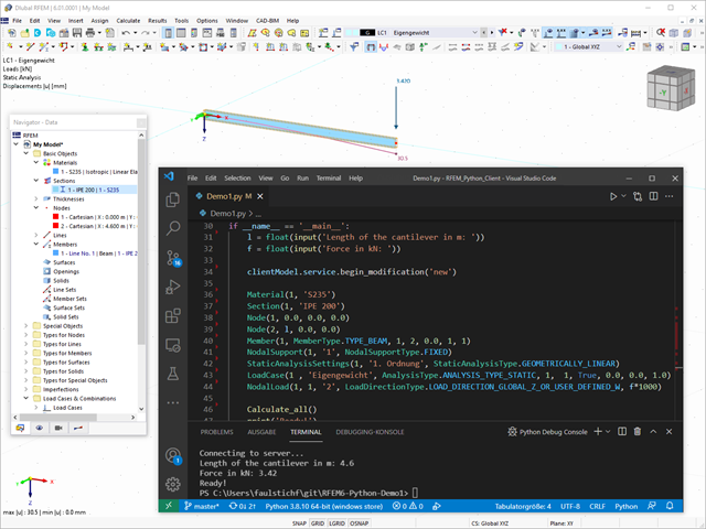
Webservice and API opens up a wide range of new possibilities for you. You can create your own desktop or web-based applications by controlling all objects included in RFEM 6 and RSTAB 9. By providing libraries and functions, you can develop your own design checks, effective modeling of parametric structures, as well as optimization and automation processes using the programming languages Python and C#. Does that sound exciting to you? Then find out more here!
More About Webservice and APITechnology takes you further, also in your daily work with RFEM / RSTAB. The new API technology Webservice allows you to create your own desktop or web-based applications by controlling all objects included in RFEM 6 / RSTAB 9. Entire libraries and numerous functions are available to you. Thus, you can easily perform your own design checks, effective modeling of parametric structures, and optimization and automation processes using the programming languages Python and C#. Dlubal Software makes your work easier and more convenient. Check it out now!
WebService and API
- Artificial intelligence technology (AI): Particle swarm optimization (PSO)
- Structure optimization according to the minimum weight or deformation
- Use of any number of optimization parameters
- Specification of variable ranges
- Optimization of cross-sections and materials
- Parameter definition types
- Optimization | Ascending or Optimization | Descending
- Application of parametric models and blocks
- Code-based JavaScript parametrization of blocks
- Optimization taking into account the design results
- Tabular display of the best model mutations
- Real-time display of the model mutations in the optimization process
- Model cost estimation by specifying unit prices
- Determination of the global warming potential GWP when realizing the model by estimating the CO2 equivalent
- Specification of weight-, volume-, and area-based units (price and CO2e)

Did you know that The structural optimization in the programs RFEM and RSTAB is a completion of the parametric input. It is a parallel process beside the actual model calculation with all its regular calculation and design definitions. The add-on assumes that your model or block is built with a parametric context and is controlled in its entirety by global control parameters of the "optimization" type. Therefore, these control parameters have a lower and upper limit and a step size to delimit the optimization range. If you want to find optimal values for the control parameters, you have to specify an optimization criterion (for example, minimum weight) with the selection of an optimization method (for example, particle swarm optimization).
You can already find the cost and CO2 emission estimation in the material definitions. You can activate both options individually in each material definition. The estimation is based on a unit for unit cost or unit emission for members, surfaces, and solids. In this case, you can select whether to specify the units by weight, volume, or area.
- A wide range of available sections, such as rolled I-sections; channel sections; T-sections; angles; rectangular and circular hollow sections; round bars; symmetrical and asymmetrical, parametric I-, T-, and angle sections; built-up cross-sections (suitability for design depends on the selected standard)
- Design of general RSECTION cross-sections (depending on the design formats available in the respective standard); for example, equivalent stress design
- Design of tapered members (design method depending on the standard)
- Adjustment of the essential design factors and standard parameters is possible
- Flexibility due to detailed setting options for basis and extent of calculations
- Fast and clear results output for an immediate overview of the result distribution after the design
- Detailed output of the design results and essential formulas (comprehensible and verifiable result path)
- Numerical results clearly arranged in tables and graphical display of the results in the model
- Integration of the output into the RFEM/RSTAB printout report
- Extensive library of rolled, parametric thin-walled and thick-walled cross-sections
- Extensible library for material properties
- Import of dxf files
- Cross-section properties of thin-walled or thick-walled cross-sections
- Ideal section properties of cross-sections consisting of different materials
- Stress analysis
- Plastic capacity design with interaction of internal forces according to the Simplex Method
- Design of reinforcement and the subsequent design of concrete cross-section in the Concrete Design add-on (see Product Feature)
- Saving cross-sections as a block
- Scripting with JavaScript
- Interface with MS Excel for exporting tables
- Connection to Webservice & API (for example, optional creation of cross-section and access to result tables)
- Printout report
RSECTION contains an extensive library of rolled sections, as well as parametric thin-walled and massive cross-sections. You can compose them or supplement them with new elements.
Graphical tools and functions allow you to model complex section shapes in the usual way common for CAD programs. The graphical input supports, among other things, the setting of arcs, circles, ellipses, parabolas, and NURBS. As an alternative, you can import a DXF file and use this as the basis for further modeling. You can easily model a section consisting of different materials with minimum effort.
Furthermore, a parameterized input allows you to enter the cross-section dimensions and internal forces in such a way that they depend on certain variables.
You can also carry out all inputs by means of a script.
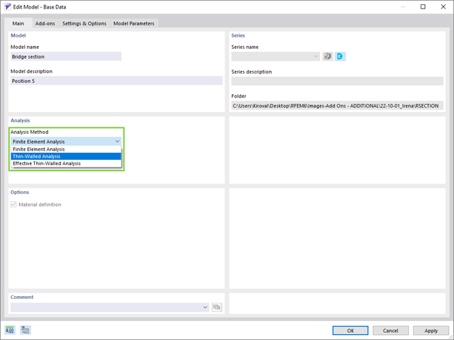
Do you want to efficiently process recurring systems? Then the parameterized input is recommended to you. You can create your models by using particular parameters and adjust them to a new situation by modifying the parameters.
If you want to manage recurring systems, you can use the parameterizable input. Models can be created using particular parameters and you can adjust them to a new situation by modifying the parameters.
- Design of members and sets of members for tension, compression, bending, shear, combined internal forces, and torsion
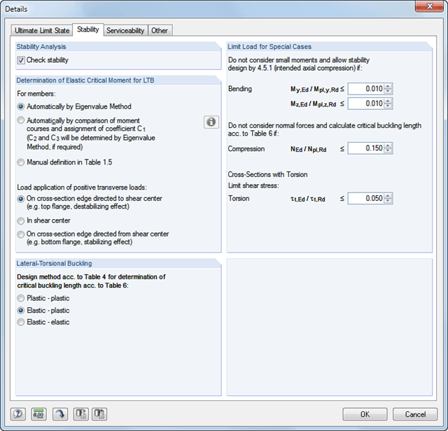
- Stability analysis of buckling and lateral-torsional buckling
- Automatic determination of critical buckling loads and critical buckling moments for general load applications and support conditions by means of a special FEA program (eigenvalue analysis) integrated in the module
- Alternative analytical calculation of the critical buckling moment for standard situations
- Optional application of discrete lateral supports to beams and continuous members
- Automatic cross-section classification (compact, noncompact, and slender)
- Serviceability limit state design (deflection)
- Cross-section optimization
- A wide range of available cross-sections, such as rolled I-sections; channel sections; T-sections; angles; rectangular and circular hollow sections; round bars; symmetrical and asymmetrical, parametric I-, T-, and angle sections; double angles
- Clearly arranged input and result windows
- Detailed result documentation including references to design equations of the used standard
- Various filter and sorting options of results, including result lists by member, cross-sections, and x-location, or by load case, load combination, and result combination
- Result table of member slenderness and governing internal forces
- Parts list with weight and solid specifications
- Seamless integration in RFEM/RSTAB
- Metric and imperial units
- Design of members and sets of members for compression, bending, shear, and combined actions
- Stability analysis of buckling and lateral-torsional buckling
- Automatic determination of critical buckling loads and critical buckling moments for general load applications and support conditions by means of a special FEA program (eigenvalue analysis) integrated in the module
- Optional application of discrete lateral supports to beams
- Automatic cross-section classification (Class 1 to 4)
- Deformation analysis (serviceability)
- Cross-section optimization
- A wide range of available cross-sections, such as rolled I-sections; channel sections; T-sections; angles; rectangular and circular hollow sections; round bars; symmetrical and asymmetrical, parametric I-, T-, and angle sections; double angles
- Optional import of buckling lengths from RF-STABILITY/RSBUCK
- Detailed result documentation including references to design equations of the used standard
- Various filter and sorting options of results including result lists by member, cross-section, x-location, or by load cases, load and result combinations
- Result table of member slenderness and governing internal forces
- Parts list with weight and solid specifications
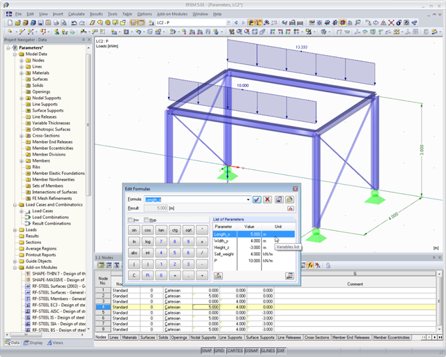
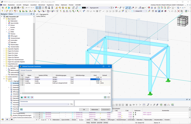
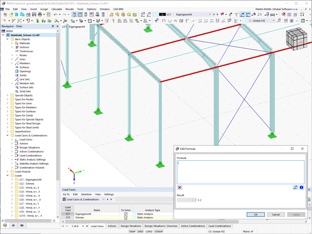
In order to work with recurring structural systems efficiently, RFEM provides the parameterized input, which can be combined with a parameterizable guideline method. Models can be created using particular parameters and adjusted to a new situation by modifying the parameters.
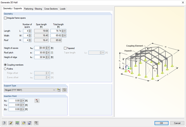
Generating tools to enter parametric models such as frames, halls, trusses, spiral stairways, arcs, or roofs. In addition, many generators allow for the creation of load cases and loading resulting from weight, snow, and wind.
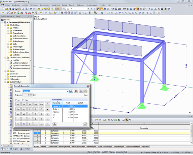
For efficient editing of recurring systems, RFEM provides parameterized input, which can be combined with a parameterizable guideline method. Models can be created using particular parameters and adjusted to a new situation by modifying the parameters.
- Design of members and sets of members for tension, compression, bending, shear, torsion, and combined internal forces
- Stability analysis of buckling, torsional, and flexural-torsional buckling
- Automatic determination of critical buckling loads and critical buckling moments for general load applications and support conditions by means of a special FEA program (eigenvalue analysis) integrated in the module
- Alternative analytical calculation of the critical buckling moment for standard situations
- Optional application of discrete lateral supports to beams and continuous members
- Automatic cross-section classification
- Serviceability limit state design (deflection)
- Cross-section optimization
- A wide range of available cross-sections, such as rolled I-sections; channel sections; T-sections; angles; rectangular and circular hollow sections; round bars; symmetrical and asymmetrical, parametric I-, T-, and angle sections; double angles
- Clearly arranged input and result windows
- Detailed result documentation including references to design equations of the used standard
- Various filter and sorting options of results, including result lists by member, cross-sections, x-location, or by load case, load and result combination
- Result tables of member slenderness and governing internal forces
- Parts list with weight and solid specifications
- Seamless integration in RFEM/RSTAB
- Cross-section designs of members and sets of members for tension, compression, bending, shear, torsion, and combined internal forces
- Stability analysis of buckling, torsional, and flexural-torsional buckling
- Automatic determination of critical buckling loads and critical buckling moments for general load applications and support conditions by means of a special FEA program (eigenvalue analysis) integrated in the module
- Alternative analytical calculation of the critical buckling moment for standard situations
- Optional application of discrete lateral supports to continuous members
- Automatic cross-section classification
- Serviceability limit state design (deflection)
- Cross-section optimization
- A wide range of available cross-sections, such as rolled I-sections, channel sections, T-sections, angles, rectangular and circular hollow sections, round bars, symmetrical and asymmetrical, parametric I-, T-, and angle sections, and many others.
- Clearly arranged input and result windows
- Detailed result documentation including references to design equations of the used standard
- Various filter and sorting options of results, including result lists by member, cross-sections, x-location, or by load case, load and result combination
- Result window of member slenderness (optional) and governing internal forces
- Parts list with weight and solid specifications
- Seamless integration in RFEM/RSTAB
- Design of members and sets of members for tension, compression, bending, shear, combined internal forces, and torsion
- Stability analysis of buckling, torsional, and flexural-torsional buckling
- Automatic determination of critical buckling loads and critical buckling moments for general load applications and support conditions by means of a special FEA program (eigenvalue analysis) integrated in the module
- Alternative analytical calculation of the critical buckling moment for standard situations
- Optional application of discrete lateral supports to beams and continuous members
- Automatic cross-section classification
- Serviceability limit state design (deflection)
- Cross-section optimization
- A wide range of available cross-sections, such as rolled I-sections; channel sections; T-sections; angles; rectangular and circular hollow sections; round bars; symmetrical and asymmetrical, parametric I-, T-, and angle sections; double angles
- Clearly arranged input and result windows
- Detailed result documentation including references to design equations of the used standard
- Various filter and sorting options of results, including result lists by member, cross-sections, x-location, or by load case, load and result combination
- Result tables of member slenderness and governing internal forces
- Parts list with weight and solid specifications
- Seamless integration in RFEM/RSTAB
- Units metric and imperial